


")
")
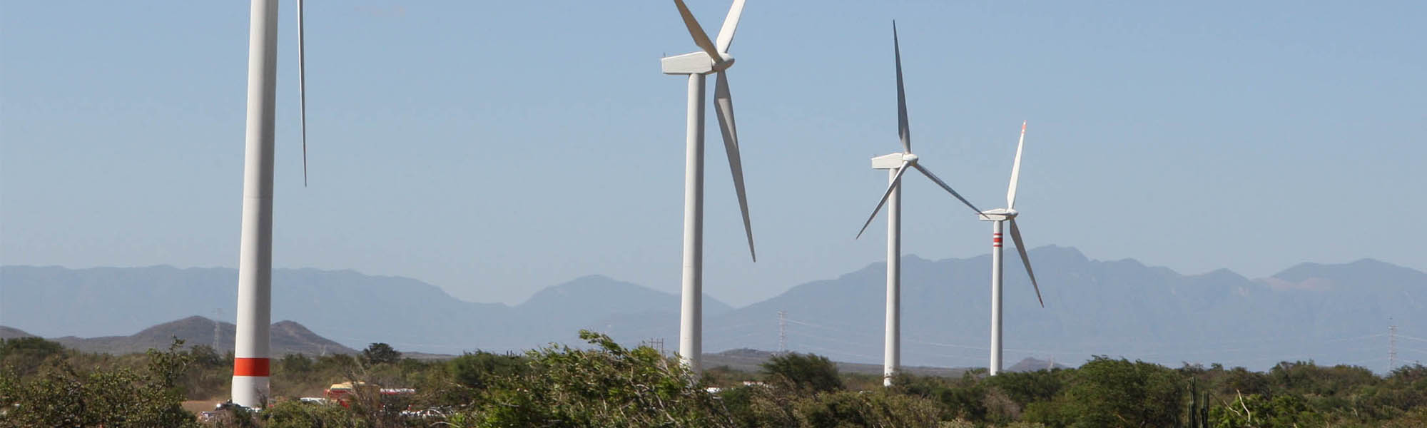


Wind farms are one of the renewable sources from which the largest developments are expected in the next future. The trend is towards increasing the number of wind farms, but also the size of each single turbine is going to grow considerably. Currently, the rated power for each turbine unit is typically smaller than 1 MW, but in the near future power ratings in the order of tens of MW’s are expected to be achieved. This is posing huge technological challenges not only with respect to turbines but also regarding the electric generators coupled to them. In fact, reliability reasons lead and often force designers to remove gear boxes (which are breakable components with complicated maintenance). As a results, the electric generator, in the direct-drive arrangement, has to revolve at such low speeds as 10-15 rpm and, thereby, it has to develop huge torques that are typically in the order of billions of N´m’s.
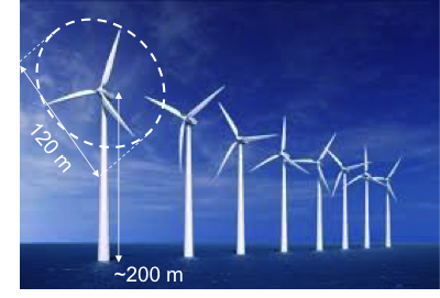
Since the electric machine volume grows with its torque, generators would be required that, if conventionally designed, could not be installed inside the wind turbine nacelle due to excessive size and weight. To overcome the issue, innovative technologies are currently under study and development to achieve the required torque levels while keeping the generator size and cost within acceptable limits. A further design goal is to increase generator reliability as much as possible due to the fact that maintenance and repair are very critical in off-shore applications.

The Dept. of Engineering and Architecture - DIA at the University of Trieste has cooperated with Nidec-ASI for the development and design of an innovative off-shore wind generator prototype (Fig. 2). The prototype has a rated power of 780 kW at 14 rpm. The design is such that, only increasing the axial length L (Fig. 2) from 0.4 m to 1 m, the power can be raised up to 2 MW with no change in the machine cross section.

In order to make the machine fault tolerant, the stator has been designed as composed of four totally independent sectors, connected to a couple of power converters interfacing the generator to the grid. In case of fault in a stator sector or in a converter, the machine can maintain its service continuity, although at reduced power, with no performance deterioration.

Pursuing modularity as a means not only to increase reliability, but also to simplify manufacturing and reducing production costs, each sector is further subdivided into elementary modules, each consisting of a stator portion with six wound teeth.
The design of stator modules is such that they are magnetically decoupled so that a fault in one of them does not significantly affect the others. Each module can also be separately built, as well as mounted and dismounted with relative ease.

The overall machine features 156 stator teeth and 136 rotor poles (Fig. 5). The choice of this fractional-slot configuration has required a multi-objective optimization, performed through finite element simulations, in order to reduce torque pulsations while maximizing the useful torque at the same time.
The need to reduce production costs and increase performance figures has let to choose a rotor design with interior permanent magnets with tangential magnetization.

Given the huge amount of design configurations to be taken into account throughout the optimization, it has been necessary to work out suitable tools to predict some quantities with no need for time-consuming finite element analyses. For this purpose, analytical or analytical-numerical procedures have been implemented capable of accurately predict many interesting performance figures (such as the stray load losses in stator conductors) without (or with limited use of) finite element analyses.
The generator prototype has been manufactured and successfully tested by Nidec-ASI (Fig. 6).
Further information about the project can be gathered through the following publications:
http://ieeexplore.ieee.org/stamp/stamp.jsp?tp=&arnumber=7112937
http://ieeexplore.ieee.org/stamp/stamp.jsp?tp=&arnumber=6317167
http://ieeexplore.ieee.org/stamp/stamp.jsp?tp=&arnumber=6317168
http://ieeexplore.ieee.org/stamp/stamp.jsp?tp=&arnumber=6184297
For any more detail, please contact dr. Alberto Tessarolo.